Environmentally Conscious and Economically Sound Machine Dismantling Forum > Gurnee
> Agriculture and Food
> Cnc 6A 2 phase 1/200 micro step motor driver controller
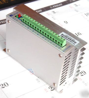
Cnc 6A 2 phase 1/200 micro step motor driver controller
NEW 2 phase hybrid stepper motor controller
Micro step max 40000 step per rev
Subdivision choosing Signal By Controller
High performance 6A 80V Stepping motor driver
Certificate of Compliance No.ACS-E05208
Low noise, high stationarity
12/8 channels constant angel and constant torque subdivision, the highest subdivision: 200
Highest response frequency: 200Kpps
The motor phase current is reduced to approximately 50% of the set current value 100ms after receiving the last pulse edge
Bipolar constant current chopping circuit
Driven current is adjustable continuously from 0.5A/phase to 6A/phase
Single power supply, voltage arrange from DC24V to 80V
Rotary switch for adjustment of the motor current
1. Please don t reverse the power input, supply voltage shouldn t exceed DC80V.
2. Input control signal is 5V, current-limiting resistance should be connected when over 5V.
3. Alarm indicator lights and the drive shuts off if the drive temperature is over 70 . It doesn t work until the temperature falls to 50 .
The heat sink is needed when overheat occurs.
4. 6 or 8 leads motors have to be used because of the special control circuit in the drive.
5. Alarm indicator lights when undervoltage (the voltage is less than DC24V) occurs.
Subdivision setting for Q2HB68MG
ON, double pulse: PU is positive pulse signal, DR is negative pulse signal
OFF, single pulse: PU is pulse signal, DR is direction signal
Self detect switch (OFF: accept pulse input, ON: send out 7.5KHz pulse)
Note: The subdivision should be set above 8 when self detect function is used
The red indicator lights when overcurrent, undervoltage, overheat occurs.
The green indicator lits when TM signal effects.
Adjust motor s phase current. Turning it in CCW will decrease the current and turning it in CW will increase the current.
Connected to +5V power supply. Driven voltage range from +5V to +24V. Current-limiting resistance is needed when over 5V.
With the falling edge of the signal PU, the motor executes an angular step. The input resistance is 220 . Low voltage 0-0.5V, high voltage 4-5V, pulse width>2.5 S.
D4=ON, PU ispositive pulse signal
D4=OFF, DR is direction signal
Change the motor s direction of rotation. Input resistance is 220 . Low voltage 0-0.5V, high voltage 4-5V, pulse width>2.5 S
D4=ON, DR is negative pulse signal
Work as the subdivision set by D0-D3 at high voltage and as 4-phase 8-step (half step) at low voltage.
When the motor current is on, the motor is at the origin position. (B, -A is on current); opto-isolated outputs (high voltage).
The motor current will be cut off and the drive stops working when it effects.
Connected + to the current limiting resistance of output signal, and connect TM to ground. Maximum driven current is 50mA and highest driven voltage is 50V.
The first is US$20.9 the another is US$12 per each
Control NEMA 34 40kg.cm step motor Running at 3000rpm