Environmentally Conscious and Economically Sound Machine Dismantling Forum > Gurnee
> Modern Stuff
> New quality basic stamp 2 programming board
New quality basic stamp 2 programming board
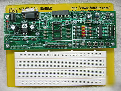
Basic Stamp 2 BS2 Project Development and Programming Board
High quality - Ergonomic Design - Easy to Use
It s the easiest and most effective microcontroller learning package in the market. Designed for student robotics, this development board is ideal for anyone who wants to learn Basic Stamps. NO soldering, only jumpers wires are needed to do most of the experiments.
High quality components, ergonomically designed, EASY TO USE !!! No Soldering needed.
This board was first designed for a local college. It is designed tough, with few loose components (No more missing component after first two lessons!! ), easy to use, yet versatile and flexible.
* Built In 5 VDC Voltage regulator
* 8 Output drivers parallel with 8 Indicator LEDs
* One pair of IR Transmitter and Receiver Circuit
* 2 Connector for Parallax Servo motors
* Multiple Voltage Outputs available on board
* High Quality Turn Pin Connectors for Jumper wires (AWG28)
* Protection for all 16 IO pins
* Large Experiment Bread Board
* 4 Switches + 1 Reset Switch
* Different combination of Connectors for IO, Bus,,,,,
'****************************************************************
' Welcome to SEBI007, below are some information to help you get started on BS-2 *
' Before you start, please make sure you have the following:
' - SEBI007 Development Board, (this board)
' - PBASIC Editor - Download from Parallax.com
' - DC adaptor (6-12VDC, center pin positive)
' - A standard serial cable for programming BS2, you may need a USB to Serial convertor
' if your PC does not have any serial or com port
' - Some wires AND cutting tools. (AWG28 single core)
' - Multimeter (0ptional though very helpful)
'Insert DC adaptor onto J2, you should see LED D1 lights up, indicating the board is ready
'Remove DC jack, install programming cable and Basic Stamp 2IC onto IC socket
'**************************************************************
' Use single core wires of appropriate length, connect
' P0-P7 (at J11) TO LED0-LED7 (J13) correspondingly,
' P0-LED0, P1-LED1,.....P7-LED7
' Start PBASIC Editor. Add the following lines of PBASIC codes
'*************************************************************
DIRS = %1111111111111111 ' Assign all I/O pin as output
OUTS = %0000000000000000 ' Set initial value of all I/O pin to HIGH
FOR loop = 1 TO 4 ' Number of loops
FOR IOPin = 0 TO 7 ' For IO Pin 0 to 7
TOGGLE IOPin ' Toggle initial state of IOPin
TOGGLE IOPin ' Toggle state of IOPin
* IMPORTANT NOTE: Basic Stamp 2 Module (BS2-IC), cable, and power adaptor are NOT INCLUDED.