Environmentally Conscious and Economically Sound Machine Dismantling Forum > Gurnee
> Tips and Advices
> Dismandling Recommendations
> Spindle tram indicator holder: cnc or bridgeport mill
Spindle tram indicator holder: cnc or bridgeport mill
*** DOWNLOAD PDF INSTRUCTIONS ***
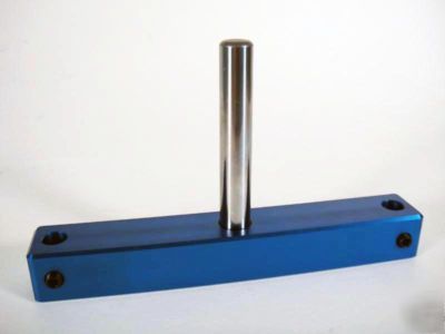
This is the simplest, most rugged design you will find anywhere.
What is so great about this Indicator Holder?
* Fool proof and precise calibration
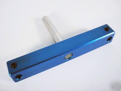
* 5.75 inches between points for maximum accuracy
* Sized to accept indicators with .375" stem
* Precision ground steel dowel pin shank (.5" x 3.75")
* Anodized 6061 Aluminum Body
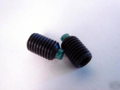
* 1/4 28 Nylon tipped set screws to protect your expensive dial indicators
* You choose the accuracy because you choose your own indicators
* Choice: people have different needs and price points. You decide if you need .001, .0005, or .0001 resolution indicators and how much you want to spend.
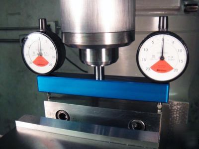
How does the user calibrate the gage once they purchase and install the indicators? (download a PDF at the top of this page)
* Calibration uses a simple "in-situ" Reference Point Process. This process is more accurate than using a surface plate to set both indicators at once. Calibrating with the gage clamped in the spindle eliminates compound error. For example, precision machine spindles are always ground with the bearings installed ("in-situ") to eliminate run-out from compound error. This calibration method uses the same principle.
* All you need is the tram gage (with indicators installed) and a mill with a .5" collet
* You can calibrate the gage even if your mill is currently out of tram, and the Reference Point Process makes this possible.
* For maximum accuracy you must recalibrate the gage every time it is secured into a collet. This calibration method is actually more precise than the repeatability of the best collets. If you do not recalibrate, the gage will read clamping error in the collet, and not the true orientation of the spindle.
1. Secure the gage in a .5" collet
2. Lower the quill onto your reference point until the first indicator reads zero. An example of a reference point is the top of your vise jaws, the mill table itself, or even the stock you will be milling.
3. Rotate the gage 180 degrees until the second indicator is touching the first reference point
4. Rotate the gage face of the second indicator until it reads zero
5. The gage is now calibrated
What motivated you to make and sell these Indicator Holders?
* I wanted the fastest, most accurate way to tram my spindle. I also wanted a gage that was fast and easy to calibrate. This design is the result.
* I also wanted to choose what type of indicator suited my needs instead of letting someone else decide, and I felt other people probably want the same thing.
* I'm a product designer by trade and have produced work for companies like Harley-Davidson and Bang & Olufsen
* I'm also a machinist, custom fabricator and used to work with Eddie Paul in Hollywood building everything from aerospace test equipment to back country fire trucks to custom cars to crazy props for film and television.
* These gage holders are made (by me) in my shop in Mountain View, California. These have been popular so I had a batch made by the CNC shop down the street. I still do the drilling, reaming, tapping, and shrink fit the shank into the holder.
What indicator do you recommend?
* Any indicator with a .375" stem will do
* Indicators with a .0400" measuring range are ideal for this application.
* I recommend the Mitutoyo #2977. It is the best balance between price and accuracy.
* Measuring range = .0400"
* Price = (approx) $60.00 each
* Returns within 7 days are accepted