Environmentally Conscious and Economically Sound Machine Dismantling Forum > Kenosha
> New m-0067E tapchanger voltage control relay
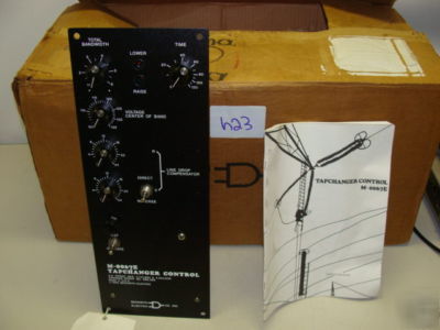
New m-0067E tapchanger voltage control relay
M-0067E Tapchanger Voltage Control Relay New in box, surplus.
General Purpose LTC Transformer Control or Replaces Westinghouse SVC and SVR Controls.
Adaptable to any LTC Transformer old or new
Meets ANSI Class 1 (1%) Accuracy Requirement
Now in Use by Leading Manufacturers as Standard Equipment
General Purpose LTC Transformer Control or
Replaces Westinghouse SVC and SVR Controls
Power: A two wire input, requiring less than 3 W at 90 to 140 V ac, provides all power requirements. The unit
should be powered from a potential transformer or from the voltage to be controlled.
Line Current: Line drop compensation is provided by a C.T. input with a 0.2 A nominal full scale rating. The
burden imposed by this input on the current source is 0.03 VA. A Beckwith Electric model M-0121 (5 A to 0.2 A)
or M-0169 (5 A or 8.66 A to 0.2 A) Auxiliary Current Transformer is available when required.
Circulating Current: Parallel operation of transformers is provided by a second C.T. input with a 0.2 A nominal
full scale rating. The burden imposed by this input on the current source is 0.005 VA. A paralleling input with a 0.2
A full scale rating gives approximately 24 V correction at approximately 90 for parallel operation with other
Two outputs drive a raise and lower motor starter relay. The starters may be any voltage up to 240 V ac. The output
contacts are rated at 2.5 A inrush current and will handle a NEMA size 1 starter or smaller.
VOLTAGE CENTER OF BAND: The center of the control band may be set to any voltage from 105 to 135 V ac.
The scale calibration accuracy is 0.5 V at 120 V ac.
TOTAL BANDWIDTH: The bandwidth control can be adjusted from 1.0 to 6.0 V. The scale calibration
TIME: The timer is adjustable from 0 to 120 sec. with a scale calibration accuracy of 10% of setting or 2 sec.,
whichever is greater. The timer starts when the voltage goes outside the band and resets within a few milliseconds
upon return to the band or when reset by an external contact in the Non-Sequential mode.
LINE DROP COMPENSATOR: The resistance compensation provides 24 V compensation for 0.2 A input in
phase with the input voltage. The reactance compensation provides 24 V compensation for 0.2 amps input at a phase
angle of 90 as chosen by the DIRECT/REVERSE switch. The magnitude and angle of each circuit is
individually set by a pair of trimpots to any accuracy limited only by the instruments used in setting. The factory
setting of magnitude will be within 5% and the phase angles within 2%. The voltage and two current circuits are
isolated from each other and do not interact.
TEST/OPERATE: When this switch is in the TEST position, the Line Drop Compensator is deactivated and the
voltage may be raised and lowered by means of an uncalibrated voltage control. An external voltmeter with a burden
of 500 per V or higher can be connected to test the band limits by observing when the RAISE and LOWER LEDs
light. No special test voltage source required.
The RAISE and LOWER LEDs light to indicate a voltage outside the band and a forthcoming tapchanger
operation as soon as the timer times out. With a slowly varying input, operation of the LEDs and initiation of timing
is very sharp with 0.2 V hysteresis. The LEDs have an expected life of 25 years.
Either of the following modes are available as determined by presence or absence of a cam switch which is closed
while the LTC is in transition.
Non-Sequential Mode: The timer resets after a tapchange, regardless of voltage.
Sequential Mode: The timer resets only after the sensed voltage is back within the control band.
Outputs are blocked from operating at input voltages below approximately 60 V ac. A proper raise output will be
obtained down to this threshold.
The M-0067E will respond to 5/8% voltage change in 0.2 sec. ensuring freedom from hunting on minimum
The unit meets the requirements of accuracy class 1 as defined in ANSI standards C57.12.30-1977 paragraph 9.3
and C57.15-4.2 when tested according to C57.15-1986 paragraph 9.4.1.
1. One- or two-step voltage reduction: Resistors for one or two pre-selected steps of voltage reduction will be
mounted on the printed circuit board at the factory.
2. Three-step voltage reduction: Resistors for a maximum of three pre-selected steps, will include the
internally-mounted resistors mentioned above, plus an additional externally-mounted resistor sized by the
3. Instantaneous (non-time delayed) voltage reduction: Circuitry is added at the factory.
This option is available for use in countries outside the continental United States and Canada. The unit will be
Input and output circuits are protected against system transients. The M-0067E will pass all requirements of ANSI/
IEEE C37.90.1-1989 defining oscillatory surge withstand capability. All inputs and outputs will withstand 1500 V
ac to chassis or instrument ground for one minute. Voltage inputs are electrically isolated from each other, from
other circuits, and from ground.
Temperature: The voltage band limits will vary no more than 0.5 V from 50 to +80 C. The timer will vary no
more than 10% of setting or 2 sec., whichever is greater.
Humidity: Stated accuracies are maintained at up to 95% relative humidity (non-condensing).
Fungus Resistance: A conformal printed circuit board coating inhibits fungus growth.
Size and Mounting: Overall dimensions are 6-3/8" x 16-1/2" (16.2 cm x 41.9 cm);
requires a panel cutout of 5-7/8" x 15-1/8" (14.9 cm x 38.4 cm).
Approximate Weight: 6 lbs (2.7 kg).
U.S. Patent 3,721,894; Canadian Patent 985,368; British Patent 1,432,607; Swedish Patent 7,301,667-7; and other