Environmentally Conscious and Economically Sound Machine Dismantling Forum > Kenosha
> Tips and Advices
> Altronix ACM8 access power & fire alarm interface board
Altronix ACM8 access power & fire alarm interface board
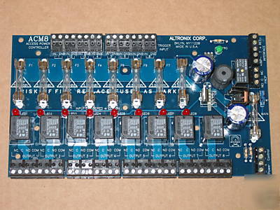
ACM8 - Card Access Lock Power Controller
Activated by an open collector sink or normally open (N.O.) dry trigger signal from a Card Access Controller, or security panel. Has eight (8) fuse protected independent switched relay outputs, to control a magnetic or electric strike locking device. The ACM8 can be powered from a single or multiple 12 or 24 volt AC/DC power source (not included). The power source selected to operate the ACM8 circuit board components, can be AC or DC and of a different voltage than the power source selected for the relay outputs. If dry contact closure output is desired instead of wet contacts, removing the fuse from any relay output circuit, will remove the power source voltage from that relay s contacts. The output will be either a N.O. or N.C. dry contact output (SPDT).
FIRE ALARM CONTROL PANEL INTERFACE (FACP)
The FACP Interface enables Emergency Egress, Alarm Monitoring, or may be used to trigger other auxiliary
devices. The Fire Alarm function can be configured for either all eight (8) outputs affected or four (4)
If the AMC8 and the locking devices are to be powered using a single power supply, connect the output
(12 to 24 volts AC or DC) to the terminals marked [- Control+].
When the use of two power supplies is desired, jumpers J1 and J2 (located to the left of the power/control
terminals) must be cut. Connect power for the ACM8 to the terminals marked [- Control +] and connect power for the locking devices to the terminals marked [- Power +].
Note: When using DC power supplies polarity must be observed. When using AC power supplies polarity
Note: For UL compliance the power supplies must be UL Listed for Access Control Systems and accessories.
The ACM8 will provide either eight (8) powered (switched and/or auxiliary), eight (8) form C , or any
combination of both powered and form C outputs.
Connect the negative (-) input of the device being powered to the terminal marked [COM]. For fail-safe
operation connect the positive (+) input of the device being powered to the terminal marked [NC]. For
fail-secure operation connect the positive (+) input of the device being powered to the terminal marked [NO].
When form C outputs are desired the corresponding output fuse (1-8) must be removed. Connect negative (-) of the power supply directly to the locking device. Connect the positive (+) of the power supply to the terminal marked [C]. For fail-safe operation connect the positive (+) of the device being powered to the terminal marked [NC]. For fail-secure operation connect the positive (+) of the device being powered to the terminal marked [NO].
(c) Auxiliary Power outputs (unswitched):
Connect positive (+) input of the device being powered to the terminal marked [C] and the negative (-) of the device
being powered to the terminal marked [COM]. This output can be used to provide power for card readers, keypads etc.
(a) Normally Open [NO] input trigger:
Inputs 1-8 are activated by normally open or open collector sink inputs.
Connect devices (card readers, keypads, request to exit buttons etc.) to terminals marked [IN] and [GND].
(b) Open Collector Sink inputs:
Connect the access control panel open collector sink positive (+) to the terminal marked [IN] and the
negative (- ) to the terminal marked [GND].
A normally closed [NC], normally open [NO] or reversal of polarity input from a fire alarm control panel
(FACP) will trigger all outputs, except when the 50/50 mode option is selected.
50/50 output mode: (Four (4) outputs with FACP disconnect with and four (4) outputs without FACP disconnect)
To program the 50/50 mode set switch SW1 to the closed position. In this mode of operation outputs 1 thru 4
will be affected when the fire alarm interface is triggered and outputs 5 thru 8 will remain unaffected.
Connect the normally open FACP trigger input to the terminals marked [+ INP] and [T].
(b) Normally Closed [NC] input:
Connect the normally closed FACP trigger input to the terminals marked [+ INP -] and install a jumper across
the terminals marked [+ INP] and [T].
(c) Output Circuit input trigger:
Connect the positive (+) and negative (-) from the FACP output circuit to the terminals marked [+ INP -]
Connect the FACP EOL to the terminals marked [+ RET -] (polarity is referenced in an alarm
condition). Jumper J3 must be cut.
Connect desired device to be triggered by the ACM8 s dry contact output to the terminals marked [NO] and [C] FACP for normally open output or the terminals marked [NC] and [C] FACP for normally closed output.
LED 1-LED 8 (Red) Output relay(s) energized. Output relay(s) de-energized.
Trg (Green) FACP input triggered (alarm condition). FACP normal (non-alarm condition).