Environmentally Conscious and Economically Sound Machine Dismantling Forum > Madison, WI
> Agriculture and Food
> Lith-ion, alk, nimh battery simulator w/ labview sftw
Lith-ion, alk, nimh battery simulator w/ labview sftw
GRAE LLC Model 101 Lithium-Ion Battery Simulator - 100709
Overview: The Model 101 Battery Simulator is used during the following:
This system emulates a single Lithium-Ion cell, Alkaline, NiMH, NiCad or pack of up to 2000maHr capability. The characteristics of a real-world cell such as battery terminal voltage, equivalent series resistance (ESR) and pulsed-load voltage decay are implemented in circuitry and software. The output is two quadrants in operation. It is possible to source or sink current to the device under test (DUT). Thus it can be re-charged like a battery.
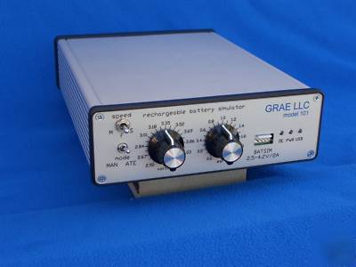
In manual mode the unit is a stand-alone battery simulation source with voltage and current outputs that can be used to calibrate or monitor a device under test. This mode is suitable for production test or where voltage and ESR settings are freely changed by the user. A DVM/DMM can be used to help set the output voltage more accurately while an Oscilloscope can be used to monitor dynamic current. In manual mode the output voltage is restricted from 2.5 to 4.2 volts, the normal range of a battery.
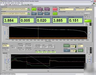
In ATE (Automated Test Electronics) mode the Model 101 has increased capabilities. The output voltage range is increased from 2.5 - 4.2 volts to 0.5 - 5.0 volts. With the included LabView software the Model 101 can respond to the device under test s power usage by adjusting the output voltage and ESR according to the amount of joules used. The terminal voltage and ESR are controlled by a data set that embodies the characteristic of a real-world battery. The data sets are installed with the software or can be generated by or for the end user. Figure 1 shows an example of a data set loaded by the LabView program.
The ESR implementation uses our Dual-Path-ESR circuit. This allows a short pulse to receive less ESR than a long pulse or a continuous load which receive the full ESR. This replicates the electro-chemical behavior of batteries.
In ATE mode an additional measurement mode is available that permits capture of short transients and pulses that would otherwise be lost in a sampled data system. This is the current integrator mode. This mode is particularly needed when testing modern digital electronics that use power sporadically and may even enter sleep modes with only short bursts of activity. Integration mode can capture 99.9% of power pulse activity
Overvoltage and over current limits are set in software by the user.
An XLS output file is generated with the measured data from the unit under test. This includes Voltage, Current, Power and Accumulated Joules.
Output Connections: The output is connected to the unit under test with a four wire connection. Regulation, ESR and Monitoring are made from this point to reduce system errors. Connection to DUT shall be made using the Battery Simulator s ground reference. Consult factory before attempting to operate unit with a floating reference. Important: damage and/or safety issues could arise with improper connections to a DUT that is floating above ground.
Output Connector Pin Assignment: Pin 1 is on the left when connector is viewed from the front.
Pin 1 Battery Simulator Positive
Pin 3 Battery Simulator Negative (not used normally)
Pin 5 Battery Simulator Negative
The mating connector is a Molex 22-01-2055 housing with 08-65-0110 crimp terminals.
Open Sense Protection: The unit will not output excessive voltage if the sense leads are open but output errors will incur. See next step to check your unit and cables for proper operation.
Operational Verification: The unit should be checked for proper operation periodically by using the provided load resistor. The USB front panel indicator will blink when connected to a computer that has the correct driver installed.
Operation with Primary Cells: for operation with primary cells use the Model 102 Battery Simulator which has higher current at lower voltages and a lower ESR range typical of these cells.
Calibration: The unit should be calibrated once per year by GRAE LLC. Contact us for info and rates.
Operational Limits: The unit shall be operated in an office, manufacturing or lab environment.
OPERATING TEMPERATURE: 5 to 30 C.
STORAGE TEMPERATURE: 20 to 50 C.
HUMIDITY: <80% @ 30 C non-condensing.
LINE VOLTAGE: 100-240VAC, 47-63 Hz
Install all software supplied on the installation DVD before connecting the Model 101. The end user will benefit from being familiar with the LabView environment or at least the National Instruments Measurement and Automation Explorer.
The Model 101 is connected as follows:
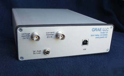
Rear Panel - Connect the USB cable to the computer. Connect a BNC male to male cable from the voltage monitor and current monitor outputs to the appropriate external equipment. For use with a DVM/DMM a female BNC to male banana plug adaptor will be needed on the external equipment end of the cable
Front Panel Remove the existing battery from the product to be tested. Connect the supplied four wire cable assembly to the point of use on your product. This is typically as close as possible to where the battery is connected normally. The two red leads form the positive lead and the two black leads form the negative lead.
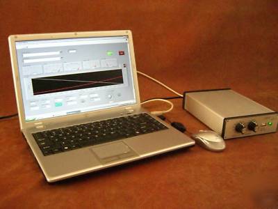
Note: Computer (not included) required for ATE operation of Battery Simulator. Manual operation and monitoring possible without computer connection for production testing or more limited use.
Specifications are subject to change without notice. Copyright 2009, GRAE LLC.
GRAE LLC: www.graellc.net, (***)-587-1588
Note: This instrumentation does not require a LabView license to use as it runs with a "runtime environment". You just have to agree to several license agreements during install.