Environmentally Conscious and Economically Sound Machine Dismantling Forum > Madison, WI
> Welding and Laser Cutting
> TIG Welding of Steel
> Controler and valve for pressurized enclosures
Controler and valve for pressurized enclosures
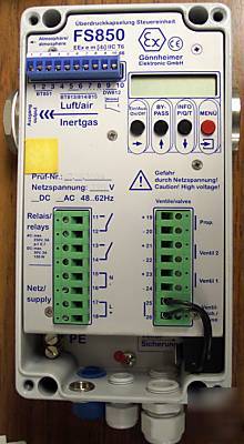
Used Controler and Valve for Pressurized Enclosures. Ex p control unit FS850S.
The pressurized enclosure system F 850 contains at least the control unit FS 850 and a solenoid valve. Each can be mounted in- or outside the enclosure.
Furthermore several remote controls (operation panels) are available to improve ergonomic of operation. It is also possible to connect intrinsically safe sensors to the control unit FS 850.
After purging, the control unit FS 850 holds the pressure inside the enclosure on at least 0.8 mbar. For that two different solenoid vale techniques are available: digital working solenoid valve (DSV) technique or proportional working solenoid valve (PSV) technique.
Digital solenoid valve technique
While purging, the DSV is activated and a big amount of purge medium flows inside the enclosure through a nozzle with a large cross-section. After purging, the control unit turns off the DSV. The leakage compensation is made by a bypass choke, with a very small adjustable cross-section (diameter 0.3 ...1 mm), inside the valve. The protective medium that flows into the enclosure now is adequate to maintain a pressure of at least 0.8 mbar. The pressure is monitored by the control unit FS 850. The maximum and minimum pressure of the enclosure is programmable.
For purging, a common and a new integrating method is available:
1. Using the traditional method, purge quantity is a product of a pre-set minimum of flow rate and time. The flow rate depends on the size of the internal nozzle (diameter 1 ...6 mm) of the valve and can be specified by matched charts. The common rule of purging must be considered: flow minimum is less than let in minus leakage loss. This purging method is named as time based purging method.
2. In contrast to the common one the integrating purging method measures the real volume flow through the enclosure outlet and adds it up to get the real purge volume. Besides, the flow rate is monitored, dependent on the size of the plate orifice of the control unit. If the flow rate sinks below its minimum, it will be ignored and it will not contribute to volume integration. Therefore we achieve a safe and economic purging method.
figure 1: consumption of protective gas
Proportional solenoid valve technique
sing proportional solenoid valve technique stops wasting protective gas. The internal proportional working sensory equipment and a proportional valve as actuator are combined to a
1. Considerable less consumption of protective gas - additional costs for proportional valve will be amortised soon
2. Increased service reliability achieved by constant pressure inside enclosure - increasing leakage caused by e.g. ageing of the enclosure will be balanced and sudden failure will be prevented
3. Almost no flow noise and only a small protective gas consumption using a solid enclosure
Another advantage using a proportional solenoid valve is; that pressure control is used even during purging. A set-point pressure will be achieved in the enclosure, while the flow volume, that leaves the enclosure, will be recorded and integrated through time, until the required purge volume is achieved. Advantages of this method are:
1. A definite pressure while purging - pressure sensitive parts of the enclosure, like membrane switch panels or windows, will not be overloaded.
2. Purge volume accuracy is achieved by integration of the purge medium flow volume on the outlet. Wasting purge medium is no more a topic of today.
Operation mode continuous flow
The control unit FS 850 has moreover the operation mode "continuous flow" implemented. This operation mode is necessary, for example, if an analyzer could produce an explosive atmosphere inside the enclosure (containment system). The operation mode continuous flow purges the enclosure permanently. After the (pre-)purging procedure (purging process) a set-point flow rate is adjusted during normal operation. The monitored flow rate minimum is adjustable. The operation mode continuous flow can be realized using 2 digital solenoid valves as well as using one proportional solenoid valve.