Environmentally Conscious and Economically Sound Machine Dismantling Forum > Milwaukee
> Welding and Laser Cutting
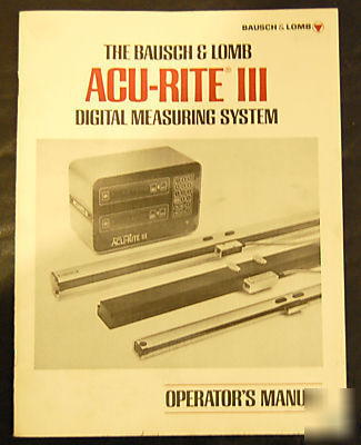
> Acu-rite iii digital readout dro operators manual
Acu-rite iii digital readout dro operators manual
GeneralInformation ....................... .. ii
Warrantyto the User. ...................... .. ii
FCCComplianceStatement.................. .. ii
1.1 How To Use This Manual 1-1
1.3 Features You Should Know About. 1-1
1.3.1 Absolute/Incremental Measurement Mode 1-1
1.3.2 Inch-to-Millimeter Direct Conversion . 1-2
1.3.4 Machine Tool Geometry (Abbe) ErrorCompensation............. .. 1.2
1.3.5 Large Scale Integrated (LSI) Circuitry. 1-2
1.3.9 Tool Offset Dimension 1-2
1.3.10 Keyboard Annunciator. 1-2
1.3.11 Membrane Control Panel 1-2
1.3.12 Switchable Resolution 1-2
1.3.13OtherFeatures ................... 1-3
2.1 Installation of Console 2-1
2.2 Electrical Connections 2-1
2.2.1 Internal Switch Settings 2-3
2.2.2 Switchable Radius/Diameter Feature. 2-4
3.2 Control Panel Description 3-1
3.2.11 Including Tool Offset Dimensions 3-3
3.3.2 Incremental Mode Operation 3-4
3.3.3.1 Example Procedure A 3-5
3.3.3.2 Example Procedure B 3-6
3.3.4 Tool Offset Operation 3-6
3.3.4.1 Example Procedure A 3-6
3.3.4.2 Example Procedure B 3-6
3.3.4.3 Example Procedure C 3-7
3.3.4.4 Example Procedure D 3-7
3.3.5 Absolute Mode Operation 3-7
3.3.6 Combined-Mode Operation 3-8
3.4 How To Use Auto Enable 3-9
SECTION 4 MACHINE TOOL ERROR COMPENSATION
4.3 Error Correction Procedure 4-3
5.2 Cover Removal Procedure 5-1
5.3 Keyboard Annunciator Volume Setting 5-1
5.4 Preliminary Troubleshooting 5-1
5.5 System Troubleshooting 5-1
5.6 Scale Assembly Troubleshooting (A-R/l and A-R/5) 5-5
5.7 Reading Head Removal and Replacement 5-5
Figure 1-1 ACU-RITE Digital Position Readout and Scale Assemblies ,
Console Electrical Connections 2-1
Figure 2-2 Internal Switch and Jumper
Figure 2-3 Decimal Point Jumper Placement on Axis Board Viewed from Back of Counter 2-3
Figure 2-4 Triple Axis Board with High/Low 2-5
Figure 3-2 Representation of Tool Offset Symbols
Figure 3-3 Table Travel Polarities (Direction) 3-3
Figure 3-4 Console Status: Power On 3-4
Figure 3-5 Console Status: Zero Reset 3-4
Figure 3-6 Console Status: Fault Indicator 3-4
Figure 3-7 Workpiece for Incremental
Figure 3-8 Console Status: Preset Value Display.. 3-5
Figure 3-9 Console Status: Clearing Preset and Display 3-5
Figure 3-10 Console Status: Digital Display 3-5
Figure 3-11 Console Status: Preset Entry,
Figure 3-12 Workpiece for Preset Procedure A 3-5
Figure 3-13 Workpiece for Preset Procedure B 3-6
Figure 3-14 Workpiece for Tool Offset
Figure 3-15 Workpiece for Tool Offset Procedure B 3-7
Figure 3-16 Workpiece for Tool Offset ProcedureC ..................... 3-7
Figure 3-17 Workpiece for Tool Offset
Procedure D ..................... 3-7
Figure 3-18 Console Status: Absolute Mode 3-8
Figure 3-19 Console Status: Preset Entry,
Figure 3-20 Console Status: Clearing Preset in Absolute Mode 3-8
Figure 3-21 Console Status: Digital Display in Absolute Mode 3-8
Figure 3-22 Workpiece for Combined Mode
Procedure ....................... 3-8
Figure 3-23 Console Status: Auto Enable
Exaggerated Abbe Error Curve of Travel on a Milling Machine with an Overhanging Table 4-1
First Step in Measuring Abbe Error. .. 4-1
Second Step in Measuring Abbe Error 4-1 Error Slope Plotted in Inches 4-2
5-1 Test Points on Power Supply Board
5-1 A-R/5 Scale Assembly Parts Identification 5-6
A-R/l Scale Assembly Parts Identification 5-7
Table 1-1 Display and Resolution of Switchable
Table 2-1 Internal Switch Settings 2-3
Table 2-2 Round-off in mm/inch Conversion 2-4
Table 3-1 Resolutions Versus Speed 3-2 Table 4-1 Standard and Displayed
Table 4-2 Standard and Displayed
Table 4-3 Switch Assembly SI Settings for
This Manual is 11 pages long and can be email PDF if Requested.
