Environmentally Conscious and Economically Sound Machine Dismantling Forum > Kenosha
> Welding and Laser Cutting
> Stick Welding
> ARM7 philips nxp LPC2368 ethernet board flash usb uart
ARM7 philips nxp LPC2368 ethernet board flash usb uart
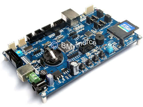
PHILIPS ( NXP ) ARM7 LPC2368 BOARD
The ARM7 LPC2368 is ARM7TDMI-S Core Board Microcontroller that uses 16/32-Bit 100 Pin (LQFP) Microcontroller No.LPC2368 from Philips (NXP). All resources inside LPC2368 is quite perfect, so it is the most suitable to learn and study because if user can learn and understand the applications of all resources inside MCU well, it makes user can modify, apply and develop many excellent applications in the future. Because Hardware system of LPC2368 includes the necessary devices within only one MCU such as USB, Ethernet, SD/MMC Memory Card, ADC, DAC, Timer/Counter, PWM, Capture, I2C, SPI, UART etc.
1 ARM7 LPC2368 Board ( Include RS232 Cable & CD Document )
* 16/32-Bit MCU ARM7TDMI-S LPC2368 from PHILIPS (NXP).
* 512K Flash Memory and 58K Static RAM internal MCU.
* 12.00 MHz Crystal, so MCU can process data with the maximum high speed at 72MHz when using it with Phase-Locked Loop (PLL) internal MCU.
* RTC Circuit (Real Time Clock) with 32.768KHz XTAL and Battery Backup.
* Support In-System Programming (ISP) and In-Application Programming (IAP) through On-Chip Boot-Loader Software via Port UART-0 (RS232).
* Circuit to connect with standard 20 Pin JTAG ARM for Real Time Debugging.
* 7-12 VAC/DC Power Supply uses Connector type as Terminal and DC-Jack with Bridge Rectifier Circuit, +5V/800mA Regulate and +3V3/3A Regulate.
* Standard 2.0 USB as Full Speed inside (USB Function has 32 End Point).
* Circuit to connect with Ethernet LAN 10/100Mb by using 1 Channel standard RJ45 Connector.
* 1 Channel Circuit to connect with SD/MMC Memory Card.
* RS232 Communication Circuit by using 2 Channel 4-PIN standard Connector.
* RS422/485 Serial Communication Circuit by using 1 Channel 6-PIN standard Connector.
* Circuit to connect with Dot-Matrix LCD with circuit to adjust its contrast by using 14 PIN standard Connector.
* 3 sets of Push Button Switch with RESET Switch.
* 2 LED Circuits to display status of testing Output.
* Circuit to generate 0-3V3 Voltage by using an adjustable Resistor Circuit for testing A/D.
* 1 Mini Speaker to generate Beep sound.
* Available 25 Bit GPIO for various applications such as A/D, D/A, I2C, SPI and Input/Output
- Header 10Pin IDE (P2[0..7]) for GPIO or Full-Duplex Serial UART.
- Header 10Pin IDE (P0[4..7],P1[20..23]) for GPIO or 4x4 Matrix Key.
- 3 Pin Header (P0[26]) for GPIO or D/A.
- 4 Pin Header (P0[24..25]) for GPIO or A/D.
- 4 Pin Header (P0[27..28]) for GPIO or I2C Bus.
- 6 Pin Header (P0[15..18] for GPIO or SPI Bus.
* User Manual NXP ARM7 LPC2368 Board.
* Tools Keil ARM Evaluation.